

THE GRID IS CHANGING. ARE OUR INVERTERS KEEPING UP?
India’s renewable expansion is changing not just where electricity comes from, but how the grid must operate to keep it reliable. India is adding renewable capacity at an unprecedented scale. But as solar, wind and battery storage become increasingly important, a critical question emerges: can the grid maintain stability as the nature of electricity generation changes?
The challenge extends beyond generating enough power. It involves maintaining voltage and frequency, responding to disturbances and ensuring reliable electricity supply. This brings one piece of equipment into sharper focus: the inverter.
A Changing Generation Mix, A Different Grid
According to the Ministry of New and Renewable Energy (MNRE), India had 299.25 GW of installed renewable capacity, including large hydropower, as of 30 September 2026. Solar accounted for 171.05 GW and wind 59.20 GW. Total non-fossil fuel capacity, including nuclear, stood at 308.03 GW.
Solar plants, battery energy storage systems (BESS) and many wind installations connect to the grid through power electronic converters. However, installed capacity does not indicate actual generation or instantaneous inverter-based penetration, which vary with weather, demand and network conditions.
Why Conventional Grids Behave Differently
Conventional thermal, hydro and nuclear generators use synchronous machines whose rotating masses provide physical inertia, initially resisting sudden frequency changes when generation and demand become unbalanced. They also support voltage regulation, reactive power and network strength.
Inverter-based resources operate through electronic controls rather than directly synchronised rotating machinery. Although modern inverters can provide frequency response and voltage support, their capabilities depend on control design, available power and operating conditions. As their share grows, these essential services must be maintained through coordinated conventional generation, storage and advanced power electronics.
Where Does the Stability Challenge Begin?
Renewables do not automatically make grids unstable, but their growing integration introduces technical challenges:
- Lower inertia: Fewer operating synchronous machines can mean less resistance to sudden frequency changes.
- Weak grids: Limited electrical strength can make stable inverter operation more difficult; short-circuit ratio (SCR) helps assess grid strength.
- Voltage stability: Requires adequate reactive power and coordinated controls.
- Power oscillations: Interactions among inverters, generators and networks can create unwanted oscillations.
- Fault response: Inverter-based plants must remain stable and respond appropriately during disturbances.
Low inertia and low system strength are distinct challenges, although they can occur together.
India Is Preparing for the Transition
At its 2 June 2026 consultative committee meeting, the Ministry of Power discussed transmission strengthening, BESS and pumped storage, STATCOMs, synchronous condensers, renewable forecasting, BESS and grid-forming inverter standards, and improved black-start capabilities.
Separately, a parliamentary response on 16 March 2026 outlined transmission planning to integrate more than 500 GW of renewable capacity by 2030.
Grid stability will require conventional generation, transmission, storage and advanced inverter controls to work together. The next question is whether the equipment connecting renewable power can actively support the grid.
That is where grid-forming inverters enter the picture.
GRID-FOLLOWING VS GRID-FORMING: THE INVERTER’S BIGGEST IDENTITY SHIFT
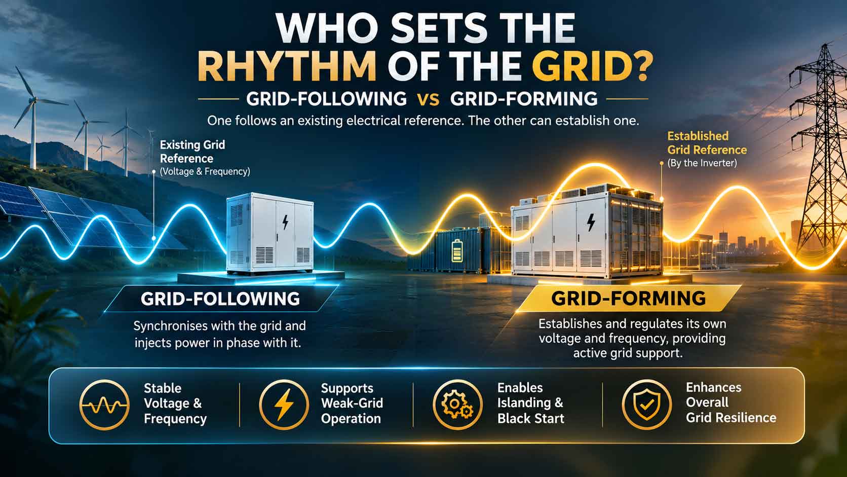
One follows an established electrical reference. The other can establish and regulate its own voltage waveform, changing how inverter-based resources interact with the grid.
The difference between grid-following (GFL) and grid-forming (GFM) inverters lies in how they establish electrical references, respond to disturbances and coordinate power. As renewable generation and battery storage expand, this distinction is becoming central to grid reliability.
Grid-Following: Synchronising with an Existing Network
GFL inverters connect to networks that provide a stable voltage and frequency reference. They use a phase-locked loop (PLL) to estimate the grid’s phase angle and frequency, synchronise with its waveform and regulate active and reactive current. They therefore generally behave as controlled current sources.
In solar plants, inverters convert DC output into AC; in BESS, the power conversion system (PCS) manages bidirectional electricity flow.
However, reliance on an external reference can create challenges in weak grids. A March 2024 IEEE Transactions on Power Systems study examined maximum transferable power under static, dynamic and thermal constraints, considering short-circuit ratio (SCR), network X/R ratio, voltage limits and PLL dynamics. It demonstrated why grid strength and control behaviour matter beyond nameplate ratings.
Grid-Forming: Establishing an Electrical Reference
GFM inverters regulate an internal voltage reference, controlling output magnitude, phase and frequency. They behave like controlled voltage sources behind an impedance and can contribute to establishing the network’s voltage and frequency reference.
This is particularly relevant where synchronous generation is limited. However, performance remains subject to semiconductor current limits, available DC-side energy, thermal constraints, protection and coordination. A GFM label alone does not guarantee islanded operation or black start.
Inside the Controls: PLL, Droop and Virtual Machines
PLL interactions with network impedance and other controls can affect GFL stability, particularly in weak grids. An April 2025 review in Computers and Electrical Engineering examined these synchronisation challenges. GFM systems commonly use droop control, linking active power to frequency and reactive power to voltage.
Virtual synchronous machine (VSM) control reproduces selected generator characteristics, including inertia-like and damping responses. However, virtual inertia is controlled behaviour, not physical rotating mass. Virtual oscillator and matching controls offer alternative approaches to grid-forming operation.
What Hardware Tests Actually Reveal
A 2024 National Renewable Energy Laboratory study by Jing Wang, Subhankar Ganguly and Benjamin Kroposki tested three commercial GFM inverters in parallel using a common protocol. All responded to voltage and frequency events, but showed stability issues while absorbing reactive power.
A separate 2024 study of a commercial single-phase GFM inverter demonstrated islanding-master capability.
However, during a frequency event, it remained connected without injecting the active power needed for grid support. Harmful voltage and frequency transients were also observed during islanding transitions. These findings apply to the specific equipment and test conditions, not all GFM inverters.
Why Both Inverter Philosophies Matter
2.5 Why Both Inverter Philosophies Matter
| Parameter | Grid-following | Grid-forming |
| Behaviour | Controlled current source | Controlled voltage source |
| Reference | Tracks existing grid voltage | Establishes internal voltage reference |
| Synchronisation | Commonly PLL-based | Internal oscillator-based or other GFM controls |
| Power response | Follows commands and configured grid support | Uses power-frequency and voltage-reactive controls |
| Weak grids | May face synchronisation challenges | Can contribute to voltage reference, subject to design |
| Islanded operation | Generally needs an external reference | Can support it when specifically designed |
| Limitations | Semiconductor and protection limits | Semiconductor and protection limits |
These are typical architectures, not universal product specifications. Advanced GFL systems can provide substantial grid support, while GFM capabilities vary by implementation. The two are complementary: GFL remains important for renewable integration, while GFM can add voltage- and frequency-forming capabilities where required.
For BESS developers and integrators, selection must therefore consider weak-grid performance, active and reactive response, current limiting, interoperability and grid-code compliance—not just rated power and efficiency.
BEYOND CONVERSION: WHAT CAN A GRID-FORMING INVERTER ACTUALLY DO?
From frequency response and voltage regulation to fault recovery and black start, the inverter is taking on a more active role in power-system operation.
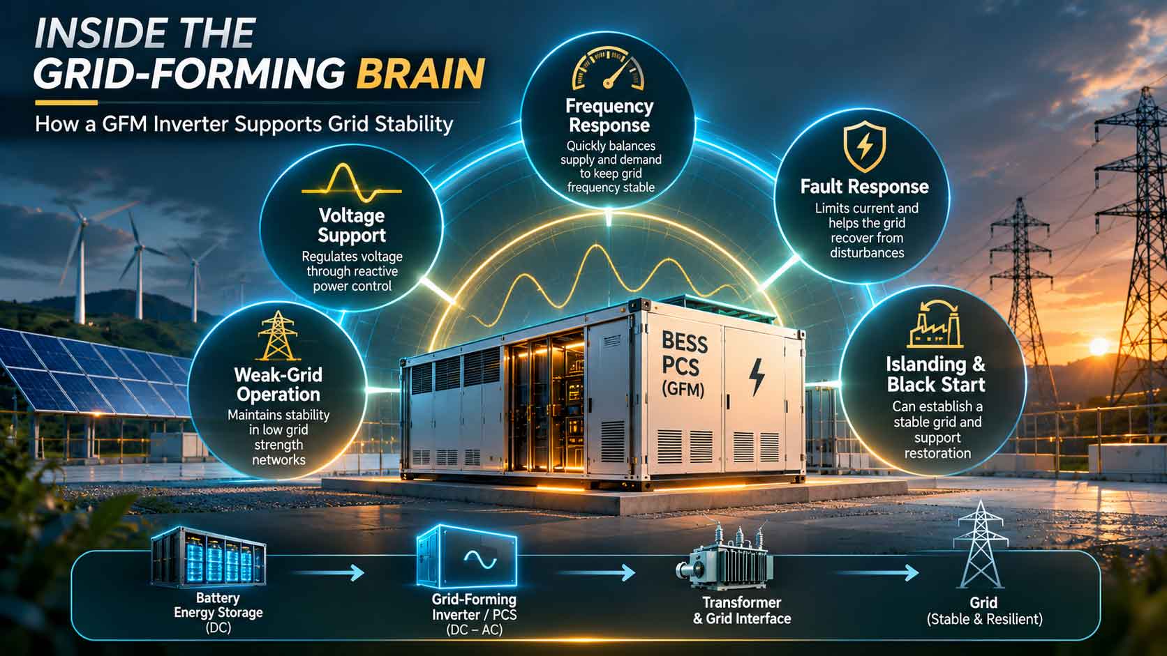
Grid-forming (GFM) technology goes beyond synchronisation. By controlling its own voltage reference, a suitably designed inverter can support frequency regulation, voltage stability, weak-grid operation, fault recovery, islanding and black start. For battery energy storage systems (BESS), this could extend their role beyond energy arbitrage. Actual performance, however, depends on battery capacity, PCS, controls, protection and grid conditions.
Frequency Response
When generation and demand become unbalanced, grid frequency changes. GFM inverters can respond through controlled active-power adjustments, while inertia-like controls emulate selected synchronous-machine characteristics. This is not physical inertia. Battery state of charge (SOC) and available power headroom determine the response; a nearly discharged battery has limited capacity to increase output.
Voltage Regulation
GFM inverters can regulate voltage and provide reactive power. However, semiconductor current limits constrain output. A 2024 hardware study of three commercial GFM inverters found that all responded to voltage and frequency events but showed stability issues while absorbing reactive power, highlighting the need to test performance in both directions.
Weak-Grid Operation
Weak grids are more sensitive to disturbances. Short-circuit ratio (SCR) helps assess grid strength, with lower values generally indicating weaker connections. Unlike grid-following inverters, GFM systems can establish a voltage reference. However, performance still depends on network impedance, controls, protection and interactions with other inverters.
Fault Ride-Through and Oscillation Damping
GFM controls can support voltage recovery and damp certain oscillations. During faults, however, converters must manage strict semiconductor current limits while maintaining synchronism. A 2024 Sandia National Laboratories report examined fault ride-through and protection-relay response. A 2025 Pacific Northwest National Laboratory study assessed two-stage current limiting through EMT simulations, including an IEEE 39-bus system.
Islanding and Black Start
A suitably designed GFM inverter can establish voltage and frequency in an islanded microgrid. Black start goes further, requiring a BESS to energise selected network components without an external supply. A 2022 National Renewable Energy Laboratory study highlighted current-limit challenges during transformer energisation and motor starting, emphasising system-level validation.
From Capability to Deliverable Service
Frequency response must specify magnitude, response time and duration; voltage support must define active- and reactive-power ranges; and fault ride-through must meet voltage-time requirements. Validation requires EMT modelling, real-time simulation, CHIL/PHIL testing, laboratory assessment and site commissioning. A GFM label alone cannot guarantee these services.
INDIA’S REGULATORY TURNING POINT: FROM ADVISORY TO TECHNICAL EXPECTATIONS
From recommendations for large battery projects to proposed requirements for renewable plants, India is beginning to define the grid-forming capabilities expected of future power infrastructure.
India’s grid-forming (GFM) transition is entering the regulatory framework through two important developments: the Central Electricity Authority’s (CEA) July 2026 advisory for large battery energy storage systems (BESS) and its September draft proposing GFM and co-located storage requirements for renewable-energy plants.
The July Advisory: A New Direction for BESS
On 10 July 2026, CEA issued an advisory calling for 100% grid-forming inverters in upcoming BESS projects of 50 MW and above.
Exemptions apply to projects whose bids were concluded by 10 August 2026 and those for which purchase orders were placed before 10 July 2026. The advisory therefore does not impose a blanket requirement on existing installations.
It also points towards verification through electromagnetic transient (EMT) studies at the design stage, commissioning demonstrations and periodic re-verification as specified by the appropriate load despatch centre. This makes GFM performance a consideration in PCS selection, system integration and project commissioning, rather than simply a product specification.
The September Draft: Extending Requirements to Renewable Plants
On 3 September 2026, CEA published the draft Technical Standards for Construction of Electric Plants and Electric Lines Second Amendment Regulations, 2026, proposing two major requirements under Regulation 106B(20):
- Renewable-energy plants commissioned after 1 July 2027: at least 15% of inverters equipped with GFM control.
- All BESS power conversion systems (PCS): equipped with GFM control in accordance with specified technical requirements.
For ground-mounted solar and onshore wind plants, the draft also proposed minimum co-located storage:
| Commissioning period | Minimum storage capacity | Duration |
| After 1 July 2027 | 10% of installed plant capacity | 2 hours |
| 1 July 2029–30 June 2031 | 10% of installed plant capacity | 4 hours |
For a 100 MW plant, the first proposed requirement translates into 10 MW of storage for two hours, equivalent to 20 MWh.
These provisions remain draft proposals, not enforceable regulations. They would become binding only through the applicable final notification in the Official Gazette.
Consultation: What Happens Next?
CEA initially set 4 October 2026 as the deadline for comments on the September draft. On 30 September, it extended the deadline to 15 October. Its public-comment archive subsequently listed the consultation as closed on 31 October 2026.
Consultation closure does not mean the proposals have become law. The final notification and any changes to applicability, technical specifications or implementation timelines remain important developments for the industry.
Separately, CEA published the draft Technical Standards for Connectivity to the Grid Regulations, 2026 on 4 August 2026. While construction standards address plant and equipment requirements, connectivity standards concern the technical conditions for connecting resources to the electricity network.
Is India’s Manufacturing Industry Ready?
On 3 February 2026, CEA issued a communication titled Manufacturing Capacity of Grid Forming Inverters in India, seeking information from manufacturers. However, this communication does not establish a verified national manufacturing-capacity figure.
The challenge extends beyond PCS assembly to power electronics, control algorithms, firmware, protection, simulation and testing.
An example of domestic equipment development is Delta Electronics India’s January 2026 agreement to supply 100 bidirectional PCS units rated at 1.1 MW each, totalling 110 MW, for multiple BESS projects. However, this should not be presented as 110 MW of verified GFM capacity without confirmation of the units’ GFM capability and deployment.
What the Regulatory Shift Means for Industry
Developers must consider GFM performance in PCS selection, tender specifications, modelling and commissioning. Manufacturers must demonstrate validated performance, while EPC contractors and integrators must coordinate batteries, transformers, protection systems and plant controls. Testing institutions will need stronger EMT modelling, simulation and hardware-in-the-loop capabilities.
India is moving from recognising GFM as a useful capability towards defining where it may be required and how it should be verified. The next challenge is translating this direction into measurable specifications, reliable testing and commercially deployable equipment.
TESTING THE GRID-FORMING PROMISE: HOW DO WE KNOW AN INVERTER IS READY?
As grid-forming requirements move closer to project specifications, simulation, laboratory testing and commissioning will determine whether an inverter can deliver reliable grid support under real operating conditions.
A grid-forming label alone cannot establish performance during faults, frequency disturbances or weak-grid conditions. Developers need evidence that an inverter can regulate its voltage reference, respond to disturbances and coordinate with other resources. The Energy Systems Integration Group’s 2025 report and a 2026 IEEE PES tutorial outline key validation methods.
EMT Simulation: Testing What Happens in Milliseconds
Electromagnetic transient (EMT) simulation captures rapid voltage and current changes, control interactions and disturbances that conventional root-mean-square (RMS) simulations may not fully represent. Studies should examine frequency and voltage changes, phase-angle jumps, faults, weak-grid conditions, multi-inverter interactions and transitions between grid-connected and islanded operation. Models must reflect actual equipment, including controls, current limits and protection logic.
A 2025 IEEE study involving a 2 MVA PV inverter, 7 MVA grid simulator and 2 MW PV emulator found that time-domain tests alone could miss resonance modes. Frequency-domain impedance scans helped identify inaccuracies in the manufacturer’s EMT model, demonstrating the importance of complementary validation methods.
Short-Circuit Ratio: Can the Inverter Operate in a Weak Grid?
Short-circuit ratio (SCR) assesses grid strength. Lower SCR generally indicates a weaker connection, where voltage is more sensitive to injected power. Testing should cover different SCR conditions, network impedance, phase-angle disturbances, oscillations and multi-inverter interactions.
However, SCR is not a universal pass-or-fail threshold. Performance also depends on network characteristics, X/R ratio, control architecture and operating conditions. The ESIG September 2025 report provides methods for evaluating GFM voltage-source behaviour against specific grid conditions.
Frequency and Voltage Response: Measuring Actual Grid Support
Frequency tests should measure response onset, rise time, active-power change, droop, sustained response and recovery. Voltage tests should assess reactive-current response, MVAr output, settling time and voltage recovery. Synchronisation after phase-angle disturbances and oscillation damping are also important.
Results must account for battery state of charge, available power and thermal limits. A battery near maximum discharge has limited additional power headroom, while a converter approaching its current limit may need to reduce active-power output to provide reactive support.
Fault Ride-Through and Current Limiting: The Real Stress Test
During grid faults, inverters must meet applicable low- and high-voltage ride-through requirements without losing synchronism or shutting down unintentionally. Unlike synchronous generators, converters have strict semiconductor current limits and must balance active and reactive current when demand exceeds them.
Testing should assess peak and sustained current, current priority, limit activation, synchronism, voltage recovery and post-fault operation. A 2025 Pacific Northwest National Laboratory study examined a two-stage current-limiting strategy through EMT simulations involving a single inverter and an IEEE 39-bus system. A 2026 review further emphasised that fault ride-through involves more than simply remaining connected.
Hardware-in-the-Loop: Bringing Real Controllers into Simulation
Controller-hardware-in-the-loop (CHIL) connects an actual inverter controller to a real-time power-system simulation. Power-hardware-in-the-loop (PHIL) connects physical power equipment to a simulated grid through a power interface. Both can test disturbances, islanding, black-start sequences and protection coordination.
However, interfaces may introduce delays, measurement errors and stability problems. A 2024 IEEE study of commercial GFM inverter PHIL testing examined these risks, including black start and loss of the last generating source. The testing platform must itself be properly designed.
Black Start and Islanding: Can the System Establish Its Own Grid?
A GFM BESS supporting restoration must demonstrate that the complete plant can energise auxiliary equipment, establish voltage and frequency without an external reference, energise transformers within current limits, pick up loads sequentially and maintain stability. This requires adequate stored energy, auxiliary power, protection and switching arrangements.
NREL research on PV-plus-storage black start highlights current-limit challenges during transformer energisation and motor starting, reinforcing the importance of validated models and hardware-based testing.
India’s Procurement Documents: Moving Towards Demonstrable Performance
The Solar Energy Corporation of India’s (SECI) Request for Selection dated 7 October 2026, covering assured peak supply of 4,800 MWh (1,200 MW × four hours) from ISTS-connected renewable projects, provides an Indian procurement example. Associated BESS requirements include:
• Operating frequency range of 47.5–52 Hz, with rated charging and discharging within 49.5–50.5 Hz.
• Low- and high-voltage ride-through, dynamic reactive-power support and voltage control.
• Primary frequency control with adjustable droop.
• SLDC/RLDC active- and reactive-power setpoints.
• Black-start and intentional island-control capability.
• RMS and PSCAD models when required by load despatch centres.
The RfS also requires accredited-laboratory IEC/BIS test certificates for batteries and power-conditioning units, alongside continuous monitoring. These are tender-specific grid-support requirements; they do not establish that every GFM behaviour has been tested or prescribe a particular GFM architecture.
From Product Testing to Plant-Level Verification
IEEE 2800.2-2026, published on 30 June 2026, establishes recommended practices for plant-level verification of inverter-based resource plants connected to bulk power systems. Separately, IEEE P2800.1 addresses GFM equipment capabilities and performance. Plant-level compliance and equipment verification are related but not interchangeable.
Validation must connect four stages: EMT and RMS model validation; laboratory testing; CHIL/PHIL hardware assessment; and commissioning of the complete plant within its actual network configuration.
The industry must move beyond asking whether an inverter is grid-forming to a more demanding question: how much performance can it demonstrate, under which conditions and for how long?
CAN INDIA MANUFACTURE THE GRID-FORMING INVERTER?
India is building a battery manufacturing ecosystem, but its next challenge is developing the power electronics, control systems and engineering capabilities that make a BESS grid-forming. The opportunity extends beyond assembling battery containers to designing, validating and owning the technology behind the power conversion system (PCS).
The PCS: A Strategic Part of the Battery Ecosystem
The PCS converts a battery’s direct-current output into alternating current, managing charging, discharging and grid interaction. While grid-following systems synchronise with an existing grid reference, grid-forming systems establish and regulate their own voltage reference.
This requires semiconductors, control hardware, embedded software, protection, thermal management and system engineering. India’s opportunity lies in developing this technology, not merely assembling converters.
Domestic PCS Manufacturing: What Is Actually Made in India?
On 6 January 2026, Delta Electronics India announced an agreement to supply 100 Make-in-India bidirectional PCS units of 1.1 MW each, totalling 110 MW, to Prostarm Info Systems for multiple BESS projects, including those associated with BSPGCL and AEML. The equipment is to be manufactured at Delta’s Krishnagiri facility in Tamil Nadu.
The agreement demonstrates domestic manufacturing and supply capability, but does not independently establish GFM controls or GFM-specific validation. Other suppliers, including Hitachi Energy India, Siemens and ABB India, also operate in the power-electronics market. Their capabilities must be assessed product by product.
The critical questions are where power stages and control boards are designed, who owns the firmware and algorithms, and whether manufacturers can provide validated EMT models and weak-grid performance evidence.
The Semiconductor Question: Who Controls the Power Stage?
Grid-forming inverters rely on power semiconductors for high-speed switching and regulation. Insulated-gate bipolar transistors (IGBTs) remain widely used in high-power converters, while silicon carbide (SiC) devices offer potential advantages in efficiency, switching performance and power density.
A 2026 McKinsey assessment estimated that India’s broader power-electronics segment was more than 90% import-dependent, with imports of approximately US$4.7 billion against domestic consumption of US$4.4 billion in 2024. This is not a GFM-specific estimate, but highlights the localisation challenge.
Dependence extends across IGBT and SiC modules, gate drivers, control boards, capacitors, inductors, sensors, processors and protection components. Localisation requires design expertise, qualification and reliable supply chains.
Building India’s Power-Semiconductor Capability
In October 2026, MeitY, the Ministry of Power and POWERGRID opened a pre-RFP consultation for indigenous SiC MOSFET-based power modules for voltage-source-converter HVDC applications.
The initiative covers device design, module engineering, fabrication, packaging, testing and qualification. It envisages development over up to 36 months and pilot procurement of approximately 13,000 validated modules for a 1,000 MW VSC-HVDC project, with emphasis on retaining intellectual property in India.
Although this is not a dedicated GFM or BESS programme, the expertise developed could strengthen the wider power-electronics ecosystem.
The Software Layer: Technology Inside the Inverter
Much of a GFM inverter’s behaviour comes from its control architecture and software. These determine voltage-reference formation, frequency response, reactive-power regulation, current limiting and interaction with other inverters.
Domestic assembly may use externally developed controls or licensed firmware, while another manufacturer may own its algorithms but import semiconductor modules. Both contribute to manufacturing, but represent different levels of technology ownership.
Deeper capability requires expertise in droop and virtual synchronous machine controls, fault response, protection coordination, multi-inverter stability, embedded firmware and EMT modelling.
Testing Infrastructure: Can India Validate GFM Products?
Manufacturing capacity alone does not establish technical readiness. GFM inverters must demonstrate weak-grid stability, fault response and coordination with other resources.
The Central Power Research Institute (CPRI) operates a grid-tied inverter testing facility in Bengaluru with a stated capacity of up to 500 kVA. It has also reported testing a 1.25 MVA grid-connected solar inverter for low-voltage, frequency and high-voltage ride-through under CEA’s 2019 grid-connectivity regulations.
This provides an important foundation, but does not establish complete GFM-specific validation covering weak-grid stability, multi-inverter interactions, advanced current limiting and black start. Conventional inverter certification and GFM validation are not interchangeable. India needs stronger real-time simulation and controller- and power-hardware-in-the-loop testing capabilities.
From Assembly to Technology Ownership
India’s manufacturing depth can be assessed across four levels:
- Equipment assembly: PCS cabinets, enclosures, electrical connections and cooling systems.
- Power-electronics manufacturing: Converter stages, control boards, protection systems and gate drivers.
- Control and software development: Domestic ownership of algorithms, firmware and simulation models.
- System validation and engineering: Demonstrating GFM performance, including weak-grid operation, fault response, islanding and black start.
India has a foundation in domestic PCS supply, semiconductor initiatives and inverter-testing infrastructure. The next step is building control-software ownership, advanced component capabilities and specialist testing expertise.
The real measure of progress will not simply be how many PCS units leave Indian factories, but how much of the technology controlling them is designed, validated and continuously improved within the country.
THE ECONOMICS OF GRID-FORMING: WHO PAYS FOR GRID STABILITY?
Grid-forming capability may strengthen the business case for battery storage, but its commercial value will depend on whether developers can recover the additional costs through project revenues and grid-service payments.
If a battery energy storage system (BESS) is expected to do more than store and discharge electricity, who pays for the additional capability? Grid-forming inverters can potentially provide frequency and voltage support, operate in weak-grid conditions and contribute to system restoration. But technical value does not automatically translate into revenue for the project owner.
The Cost of Grid-Forming: What Changes for Developers?
A BESS investment includes battery cells, power conversion systems (PCS), transformers, electrical infrastructure, cooling, fire protection, software, engineering and commissioning. Grid-forming capability may add costs through advanced inverter controls, validated simulation models, specialised testing and more extensive commissioning.
However, there is no verified industry-wide cost premium applicable to every GFM inverter. The additional expenditure depends on converter architecture, control platforms, power rating and whether equipment is upgraded or designed for GFM operation from the outset.
Developers must assess the impact on total project cost alongside battery degradation, augmentation, efficiency, auxiliary consumption, availability guarantees and financing costs.
Falling BESS Tariffs, Rising Commercial Pressure
A May 2026 report by the Institute for Energy Economics and Financial Analysis (IEEFA), prepared with JMK Research and Analytics, examined India’s standalone BESS allocations during 2025. It found that:
• India allocated 10.4 GW of standalone BESS capacity in 2025.
• The lowest discovered tariff for two-hour systems reached ₹1.48 lakh/MW/month, while four-hour systems reached ₹2.85 lakh/MW/month.
• Nearly 75% of allocated two-hour BESS capacity fell into the report’s at-risk viability category.
• Lenders typically expected project IRRs of 15–20%.
The report also found that BESS tariffs declined by more than 71% between 2022 and 2025, compared with a 36% reduction in battery-pack prices.
This gap puts pressure on developers competing at lower tariffs while managing equipment, financing and operating costs. Additional GFM requirements could intensify that pressure if higher technical expenditure is not reflected in procurement or payment structures.
What Additional Value Can GFM Deliver?
A GFM-enabled BESS can potentially provide frequency response, reactive-power-based voltage support, weak-grid support, islanded operation and black-start services. These capabilities can improve system flexibility and reliability.
But two forms of value must be separated: revenue earned by the project owner through a contract, tariff or ancillary-service mechanism, and wider system benefits such as improved reliability, reduced congestion or deferred network investment. Unless the latter are recognised through payment or procurement arrangements, they do not automatically become bankable project revenue.
Ancillary Services and Revenue Stacking
India’s CERC Ancillary Services Regulations, 2022, recognise eligible energy storage resources for participation in Secondary Reserve Ancillary Services (SRAS), subject to technical and operational conditions. Requirements include:
- Minimum response capability of 1 MW.
- Bidirectional communication with the relevant regional load despatch centre, along with metering and SCADA telemetry.
- Response to an SRAS signal within 30 seconds.
- Delivery of the full capacity obligation within 15 minutes, sustained for at least 30 minutes.
For non-generating SRAS providers, performance-based incentives range from 10 to 50 paise/kWh. Providers achieving at least 95% performance qualify for the highest incentive band.
This creates an existing route for eligible batteries to earn through frequency-related services. However, SRAS is not exclusive to GFM batteries, and the regulations do not provide a separate payment simply for possessing GFM capability.
BESS projects may also combine energy arbitrage, peak supply, renewable firming, frequency regulation, reserves, voltage support, black start and network support. This is known as revenue stacking. However, all services cannot necessarily be delivered simultaneously. A battery committed to full-power peak discharge may have limited capacity available for frequency response. A credible financial model must account for power limits, state of charge, cycling, degradation and contractual obligations.
Government Support: Improving Storage Economics
Government incentives have played an important role in India’s BESS market. The VGF scheme approved in September 2023 initially targeted 4 GWh of storage, with financial support of up to 40% of project capital cost; its supported capacity was subsequently expanded.
In December 2025, the Ministry of Power reported that discovered BESS costs had fallen from approximately ₹10.18/kWh in 2022–23 to ₹2.10/kWh for two daily cycles in recent procurements without VGF. At an assumed 1.5 cycles per day, the estimated cost was approximately ₹2.80/kWh. The Ministry also reported ₹5,400 crore of support for 30 GWh through the Power System Development Fund.
On 4 November 2026, the Union Cabinet approved a further ₹14,500 crore VGF scheme for 92 GWh of grid-scale storage, comprising:
- 30 GWh BESS, 60 GWh pumped storage and 2 GWh emerging storage technologies.
- Estimated investment of ₹97,600 crore.
- Implementation during FY2026–27 to FY2030–31.
- Minimum 40% Domestic Content Requirement for BESS projects.
The scheme can expand demand for advanced PCS equipment and grid-integration engineering, but it is not a dedicated subsidy for GFM inverters.
The Missing Link: Who Pays for Grid Stability?
A battery may provide voltage support, improve weak-grid operation or contribute to restoration without receiving a separate payment for those services under a conventional storage contract.
Possible future market mechanisms include dedicated voltage-support contracts, procurement of GFM capability in weak-grid locations, payments for reserved power and energy, performance-based compensation and long-term black-start service agreements. These are potential market-design options, not existing universal payment arrangements in India.
For lenders, bankability will also depend on equipment guarantees, battery degradation and augmentation assumptions, validated grid-support performance, accurate simulation models, long-term software support, revenue certainty and clear allocation of performance risks. The IEEFA–JMK assessment reinforces that financial closure, execution and payment security remain challenges in India’s standalone BESS market.
Making Grid Stability Bankable
For manufacturers, GFM creates opportunities to offer advanced PCS platforms alongside software, commissioning and lifecycle support. Developers must build financial models that account for additional equipment costs and realistic service revenues. Regulators and utilities must identify where these capabilities are needed and establish procurement arrangements that reward measurable performance.
A battery that shifts electricity between hours serves one purpose. A battery that can also regulate voltage, respond to frequency disturbances, support weak networks and contribute to restoration could become a much more valuable grid asset.
The commercial challenge is to ensure that this additional value is measured, contracted and paid for.
THE ROAD AHEAD: CAN GRID-FORMING BECOME THE NEW GRID STANDARD?
As renewable generation and battery storage expand, the future grid will depend not only on how much electricity can be generated and stored, but also on how effectively inverter-based resources can support the system.
India’s transition towards grid-forming technology is gaining momentum. The July 2026 CEA advisory for large BESS projects, September draft construction standards and growing emphasis on testing indicate that inverter performance is becoming an increasingly important part of power-system planning.
India’s Grid Transition Is Gathering Scale
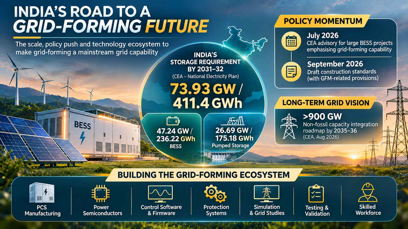
The Central Electricity Authority’s National Electricity Plan estimates that India will require 73.93 GW/411.4 GWh of energy storage by 2031–32. This includes 47.24 GW/236.22 GWh of BESS and 26.69 GW/175.18 GWh of pumped storage. The CEA’s August 2026 transmission planning update also outlines a roadmap for integrating more than 900 GW of non-fossil capacity by 2035–36.
This expansion will require more than additional storage installations. Batteries, renewable plants, conventional generators and transmission infrastructure must operate together to maintain grid stability. Grid-forming inverters could become an important part of this transition.
No Single Technology Can Stabilise the Grid
Grid-forming inverters are not a replacement for every conventional grid-support technology. Synchronous generators provide physical inertia and short-circuit current; synchronous condensers support voltage regulation and system strength; batteries offer fast power response and energy storage; and GFM inverters can establish and regulate voltage and frequency references under suitable conditions.
Transmission expansion, reactive-power compensation, forecasting, protection upgrades and coordinated controls will remain equally important. Deployment must reflect the electrical requirements of individual networks.
Interoperability and Standards Will Matter
A single GFM inverter may perform well in laboratory testing, but multiple units from different manufacturers can interact through their control algorithms, protection settings and current-limiting strategies.
The International Energy Agency’s State of Energy Innovation 2026 highlights unresolved questions about how much GFM capability is needed, where it should be deployed and the shortage of multi-asset, multi-vendor demonstrations.
International standards are also evolving. IEEE 2800.2-2026 addresses plant-level testing and verification of inverter-based resource installations, while the separate IEEE P2800.1 work focuses on grid-forming equipment capabilities and performance. India needs a consistent framework that connects equipment testing with actual plant-level performance.
Building India’s Complete Technology Ecosystem
India’s opportunity extends beyond manufacturing PCS units. It includes developing control software, firmware, power semiconductors, protection systems, simulation models and advanced testing capabilities. The CEA’s February 2026 communication seeking information on domestic GFM manufacturing capacity indicates that industrial readiness is already part of the policy discussion.
The next step is to understand how much technology is genuinely developed and owned domestically and where investment in engineering and validation is needed.
From Regulation to Operational Reality
Utilities and grid operators must identify where GFM resources can deliver the greatest benefit through studies of network strength, voltage stability, fault levels and restoration requirements. Developers must integrate these capabilities during project design, while manufacturers must demonstrate reliable performance under actual operating conditions.
India’s July advisory and September draft mark important regulatory developments, but successful deployment will depend on testing, monitoring, commissioning and operational learning.
Grid-forming technology is not a complete solution on its own. Its success will depend on reliable equipment, validated models, viable economics, consistent standards and coordination across the electricity system.
The next generation of electricity infrastructure will be defined not only by how much power India can generate, but by how intelligently it can control, balance and sustain that power.
 Electrify your feed! Click here to join our Whatsapp group and to get the latest updates, expert insights, and innovations driving India’s energy storage revolution.